Serial
Serial->Status
|
Filed |
Description |
|
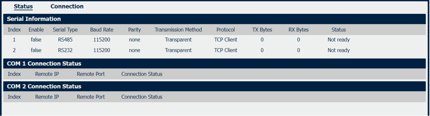
Displays status of current serial function. |
|
Displays the serial type of COM port. |
|
Displays the serial port baud rate. |
|
Displays the serial port parity. |
|
Displays the transmission method of this serial port. |
|
Displays the protocol used by this serial port. |
|
Displays the amount of transmitted data of this serial port. |
|
Displays the amount of received data of this serial port. |
|
Displays the connection status of this serial port. |
|
Displays the Remote IP address of the current COM1/2 connection. |
| Remote port | Displays the Remote port number of the current COM1/2 connection. |
| Connection status | Dispalys the status of current COM1/2 connection. |
Serial->Connection
|
Field |
Description |
|
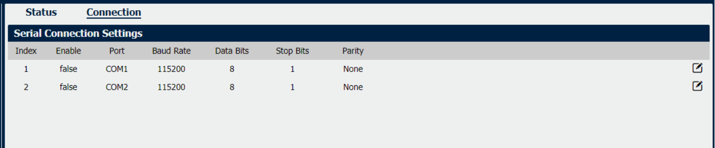
Displays status of current serial function. |
|
Displays the serial type of COM port. |
|
Displays the serial port baud rate. |
|
Displays the serial port Data Bits. |
|
Displays the serial port Stop Bits. |
|
Displays the serial port parity. |
Connection Settings
|
Field |
Description |
|
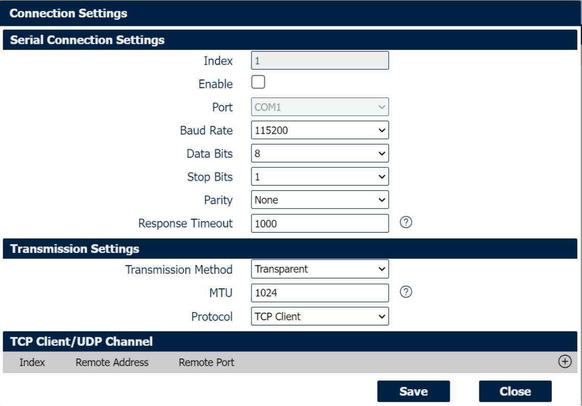
Select the serial port baud rate. Supported values are 1200, 2400, 4800, 9600, 19200, 38400, 57600,115200, 230400, 460800 or 921600. |
|
Select the values from 8. |
|
Select the values from 1 or 2. |
|
Select values from none, even, odd. |
|
Select the transmission method for serial port. Optional for “Transparent”, “Modbus RTU Gateway” and “Modbus ASCII Gateway”. |
| MTU | Maximum Transmission Unit, maximum packet size allowed to be transmitted. Should be left as default value of 1024 in most cases. |
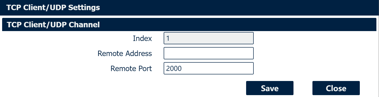
| Protocol | Select the mode for Serial IP communication. Supported modes are UDP, TCP Server, or TCP Client. Above window displays these settings when you select TCP Client on Protocol. |
| Remote Address | Enter the IP address of the remote server. |
| Remote Port | Enter the port number of the remote server. |
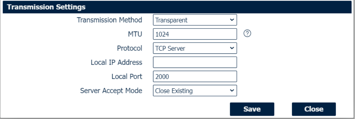
When you select TCP Server on Protocol, the window displays the settings as below.
TCP Settings
|
Field |
Description |
|
Enter the IP Address of the local endpoint. |
|
The port number assigned to the serial IP port on which communications will take place. |
|
Select the Server accept mode. Selections are “Close Existing” and “Close New”. |
When you select UDP on Protocol, the window displays the settings as below.
UDP Settings
|
Field |
Description |
|
Enter the IP Address of the local endpoint. |
|
The port number assigned to the serial IP port on which communications will take place. |
|
Enter the IP address of the remote server. |
|
Enter the port number of the remote server. |
Digital IO
Digital IO->Status
|
Field |
Description |
|
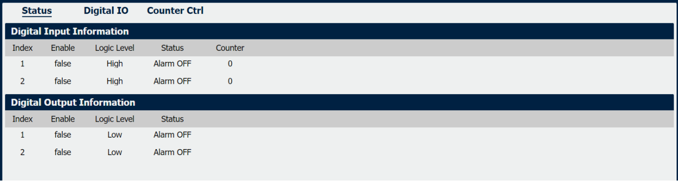
Displays status of current digital IO function. |
|
Displays the electrical level of digital IO port. |
|
Displays the alarm status of digital IO port. |
|
Display the number of digital input port counters. |
Digital IO->Digital Input
|
Field |
Description |
|
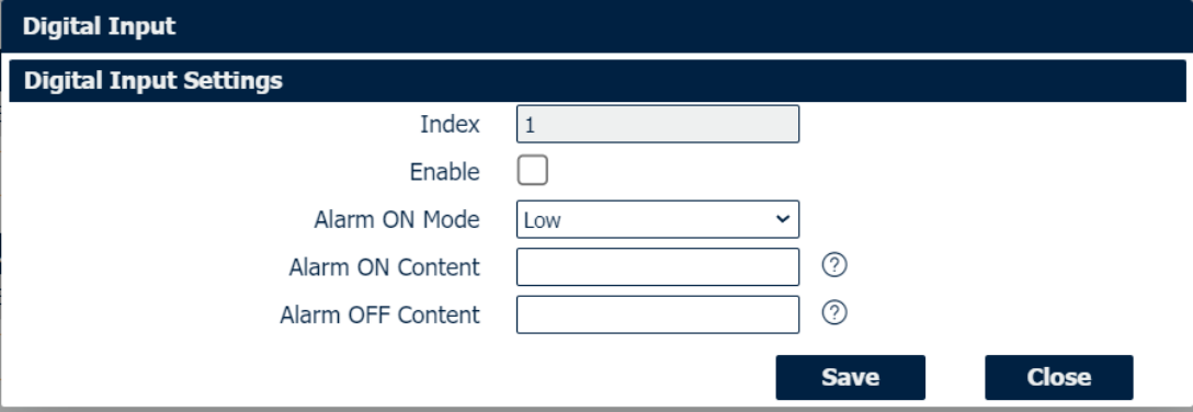
Check this box to enable digital Input function. |
|
Select the electrical level to trigger alarm. Option are “Low” and “High”. |
|
Specify the alarm on content to be sent out via SMS message. |
|
Specify the alarm off content to be sent out via SMS message. |
Digital IO->Digital Output
|
Field |
Description |
|
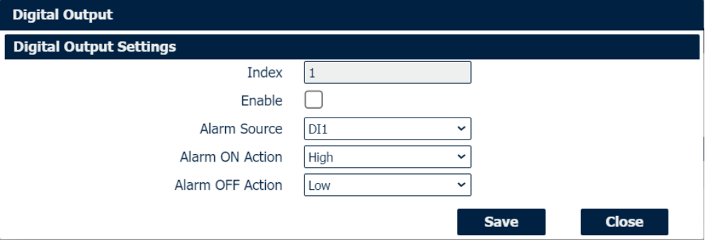
Check this box to enable digital output function. |
|
Select from “DI1”, “DI2” or “SMS”, Digital output triggers the related action when there is alarm comes from Digital Input or SMS. |
|
Select from “High”, “Low” or “Pulse”. High means high electrical level output. Low means low electrical level output. Pulse will generate a square wave as specified in the pulse mode parameters when triggered. |
|
Initiates when alarm disappeared. Select from “High”, “Low” or “Pulse”. High means high electrical level output. Low means low electrical level output. Pulse will generate a square wave as specified in the pulse mode parameters when triggered. |
|
This parameter is available when select “Pulse” as “Alarm ON Action/Alarm OFF Action”. The selected digital output channel will generate a square wave as specified in the pulse mode parameters. |
Counter Ctrl
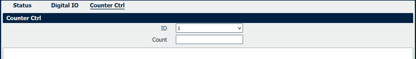
Counter Ctrl
|
Field |
Description |
|
Select serial connection Index, 1 or 2. |
|
Set the number of digital input port counters by manually. |