1 LED Indicators
|
Name |
Color |
Status |
Description |
|
SYS |
Green |
Slow Blinking (500ms duration) |
Operating normally |
|
Fast Blinking |
System initialing |
||
|
Off |
Power is off |
||
|
NET |
Green |
On |
Register to Highest priority network service (depend on Radio, e.g. Radio support LTE as Highest priority network). |
|
Fast Blinking (500ms duration) |
Register to Non-Highest priority network service (depend on Radio, e.g. Radio support LTE as Highest priority network, then WCDMA and GPRS is non-highest priority network). |
||
|
Off |
Register failed |
||
|
USR: SIM |
Green |
On |
Router is trying cellular connection with SIM1 |
|
Fast Blinking (250ms duration) |
Router is trying cellular connection with SIM2 |
||
|
Off |
No SIM detected |
||
|
USR: Wi-Fi |
Green |
On |
Wi-Fi is enabled but without data transmission |
|
Blinking |
Wi-Fi is enabled and data transmission |
||
|
Off |
Wi-Fi is disable or initialize failed |
||
|
Signal Strength Indicator |
Green |
On, 3 LED light up |
Signal strength (21-31) is high |
|
On, 2 LED light up |
Signal strength (11-20) is medium |
||
|
On, 1 LED light up |
Signal strength (1-10) is low |
||
|
Off |
No signal |
2 Ethernet Port Indicator
|
Name |
Status |
Description |
|
Link indicator |
On |
Connection is established |
|
Blinking |
Data is being transmitted |
|
|
Off |
Connection is not established |
NOTE:There are two LED indicators for each Ethernet port. Due to the chipset design NR500 router would only light up the green one(Link indicator) on left side, the right LED is Off without meaning.
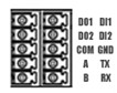
3 PIN Definition of Terminal block
|
PIN |
RS232 |
RS485 |
DI |
DO |
Direction |
|
1 |
-- |
-- |
-- |
DO1 |
Router-->Device |
|
2 |
-- |
-- |
-- |
DO2 |
Router-->Device |
|
3 |
-- |
-- |
-- |
COM |
-- |
|
4 |
-- |
A |
-- |
-- |
Router<-->Device |
|
5 |
-- |
B |
-- |
-- |
Router<-->Device |
|
6 |
-- |
-- |
DI1 |
-- |
Router<--Device |
|
7 |
-- |
-- |
DI2 |
-- |
Router<--Device |
|
8 |
GND |
-- |
-- |
-- |
-- |
|
9 |
TX |
-- |
-- |
-- |
Router-->Device |
|
10 |
RX |
-- |
-- |
-- |
Router<--Device |
4 Power Input
|
PIN |
Description |
|
V+ (Red line) |
Positive |
|
V- (Yellow line) |
Negative |
|
PGND |
GND |
5 Reset Button
|
Function |
Action |
|
Reboot |
Press the RST button within 3s under operation status |
|
Factory Reset |
Press the RST button between 3s to 10s, all LEDs blink few times then reboot the router manually. |
|
Run Normally |
Press the RST button more than 10s, router will run normally without reboot or factory reset. |