This page provides the online Quick Start Guide (QSG) for the NR500-Std industrial LTE router. It offers a general introduction to the device, including descriptions of the front and rear interfaces, instructions for assembling the hardware, steps for accessing the router for the first time, key technical specifications, and important safety notes.
Before operating the NR500-Std, it is advisable to review this Quick Start Guide to ensure proper setup and use. A printed copy of the QSG is also included inside the product package for your convenience.
1 Images
 |
 |
 |
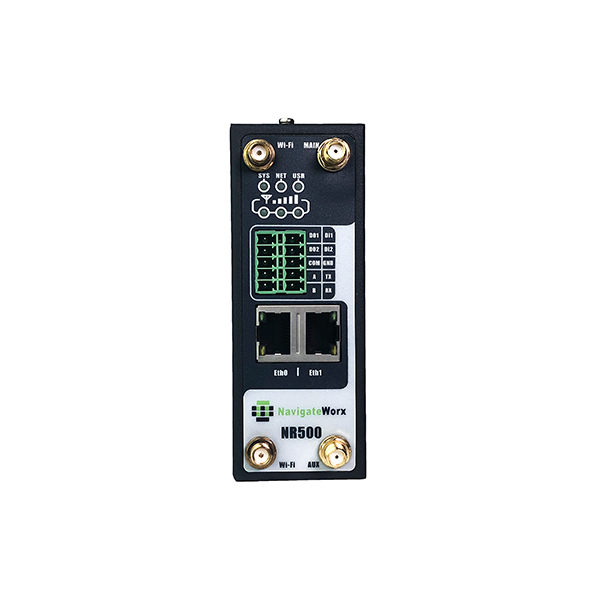
1.1 Front View
Dimension: 106mm x 106mm x 40mm (excluding antenna)
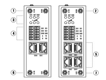 |
1 - Wi-Fi Antenna 2 - MAIN Cellular Antenna 3 - LED Indicator 4 - Serial port & DIDO 5 - Ethernet port 6 - Wi-Fi Antenna 7 - AUX Cellular Antenna |
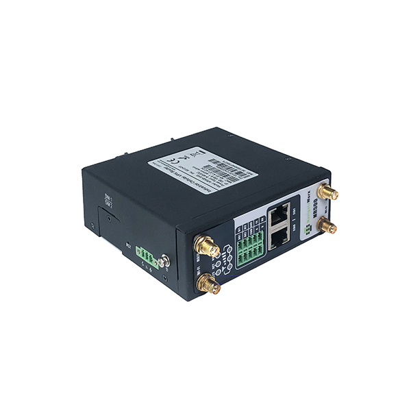
1.2 Top View
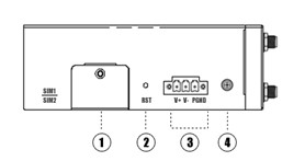 |
1 - SIM Card Slot 2 - Reset Button 3- Power Connector 4 - Grounding Stud |
2 Package Checklist
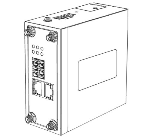
2.1 Included equipment
 |
 |
 |
 |
| Navigateworx Router | Terminal block for power supply | Terminal block for serial/DIDO | Ethernet Cable |
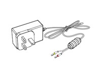
2.2 Optional Accessories
 |
 |
 |
 |
 |
 |
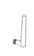
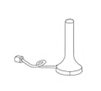
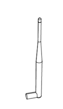
| Power adapter | Cellular antenna (x2) | Cellular antenna(x2) | Wi-Fi antenna (x2) | Wi-Fi antenna(x2) | DIN rail mounting kit |
3 Hardware Installation
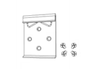
3.1 Install SIM cards
|
Use a phillips-head screwdriver to remove the SIM slot cover. Insert the SIM card(s) into the SIM sockets. Replace the SIM slot cover. |
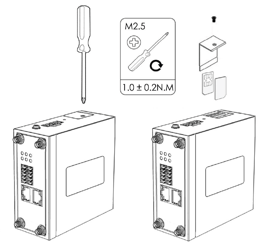 |
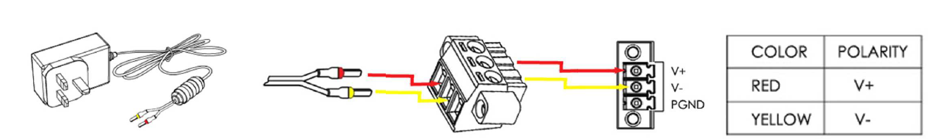
3.2 Install power terminal block
Remove the pluggable connector from the unit, then lossen the screws for the locking flanges as needed.
Connect the wires of the power supply to the terminals.
3.3 Install the Antenna
According to different models.
| Connect the cellular antenna to the MAIN and AUX connector on the unit. | 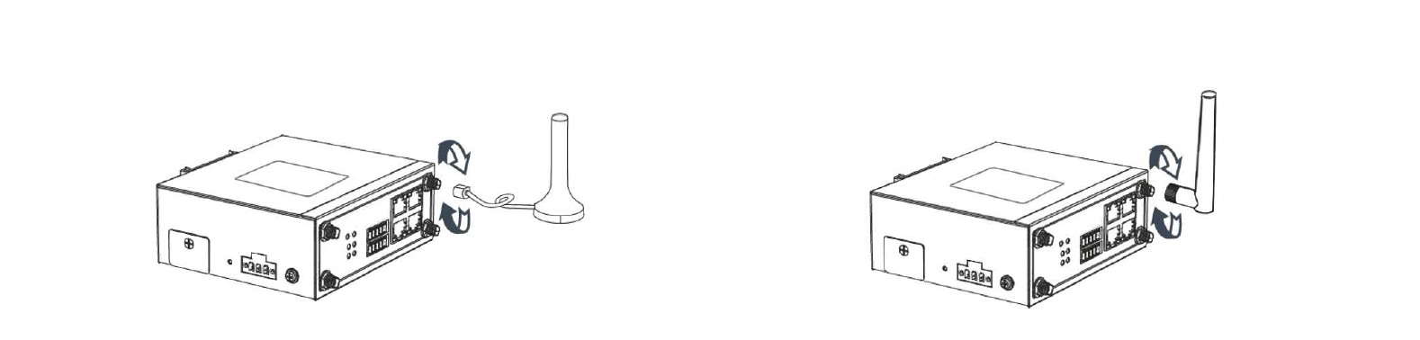 |
| Connect the Wi-Fi antenna to the MAIN and AUX connector on the unit. | 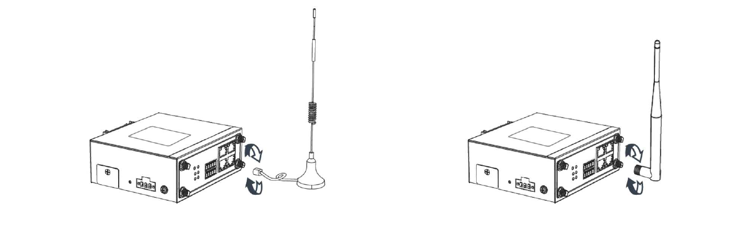 |
4 Power on the Router
| Connect one ned of the Ethernet cable to the LAN on the unit and the other end to a LAN port on a PC. Connect the AC power to a power source. Router is ready when SYS LED is blinking. | 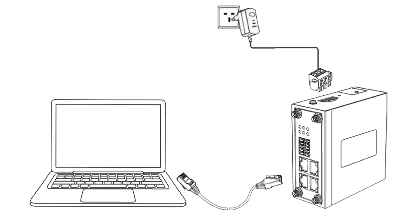 |
5 Login to web page
| Please configured your PC to automatically get IP address. Otherwise, make sure your PC can connect to the network 192.168.5.1/24. | 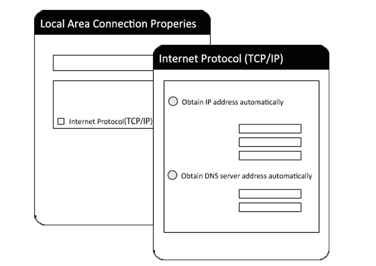 |
| Enter https://192.168.5.1 into the address of the web broswer. Use <admin> as username and unique password located on the product label. | 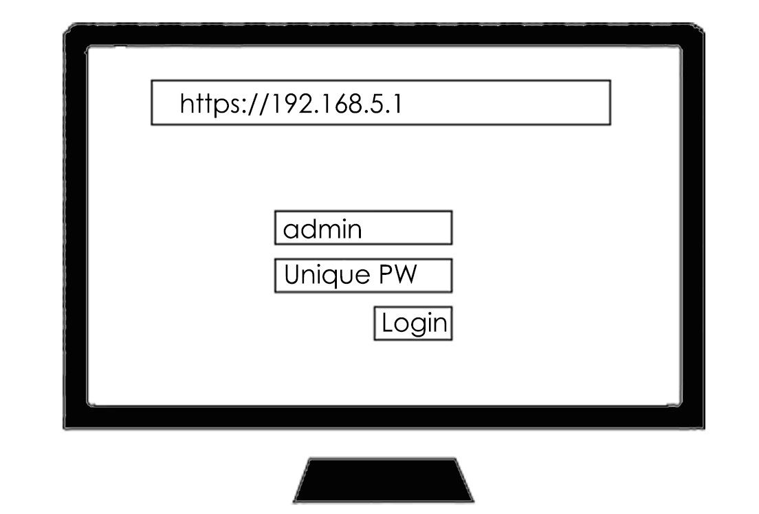 |
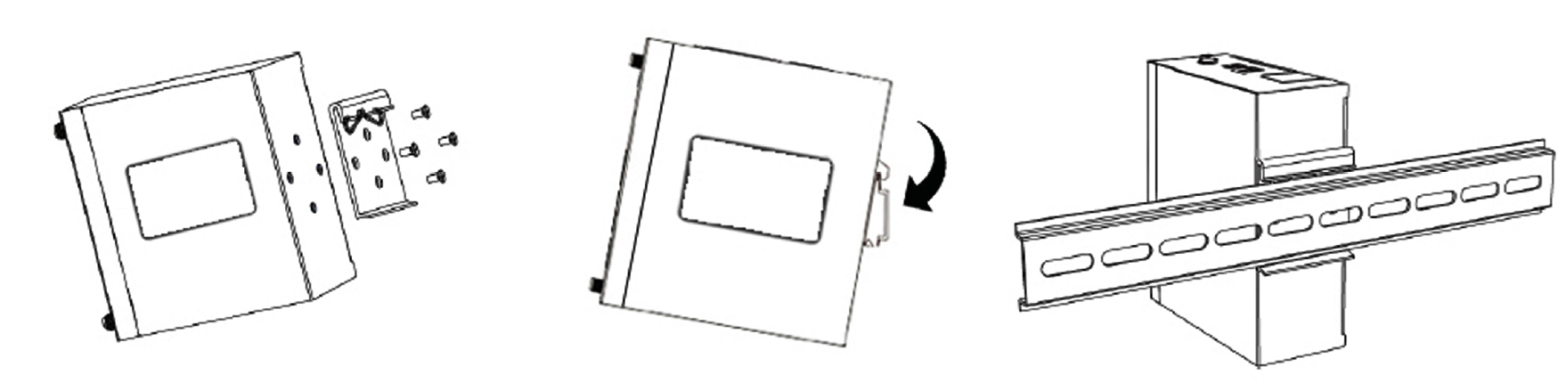
6 Mounting
| Use 4pcs of M3x6 flat head phillips screws to fix the DIN-rail to the router. Insert the upper lip of the DIN-rail into the DIN-rail mounting kit. Press the router towards the DIN-rail until it snaps into place. | 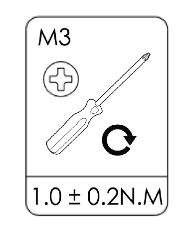 |